Company
Markets
Brands
Products
Contact
Join
MW
Company
Markets
Brands
Products
Contact
Join
MW
Electrical conductors
developed for
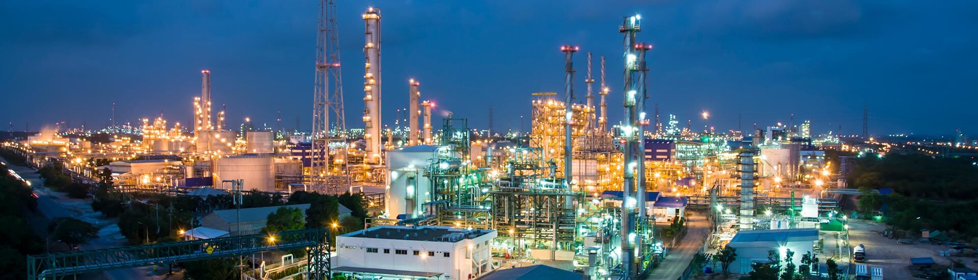
Oil & gas
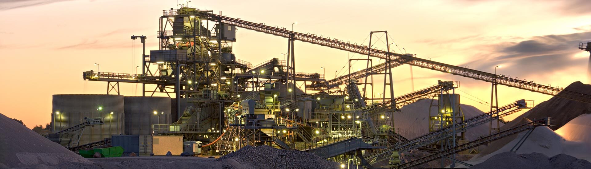
Mining
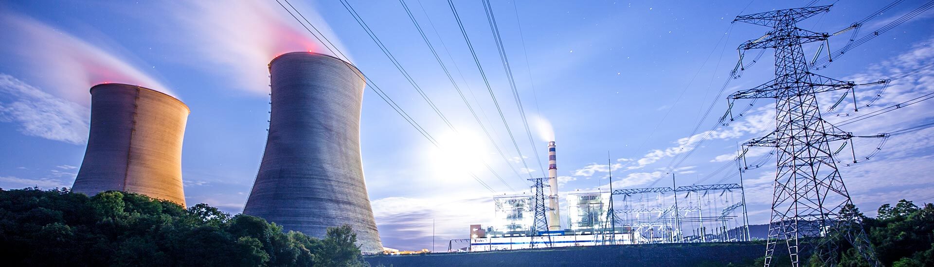
Energy
infrastructure and transport
industry and construction
Our Brands
Electronic Instrumentation
Power & Control (mm2-AWG)
Instrumentation, Power and Control (Fire Resistant)
Instrumentation, Power and Control (LSZH)
Automation and Communication
General Installations
Oil & Gas
Power and Control with high performance shield
Fire Alarm
Increased Resistance
Variable Frecuency Drive (VFD)
Photovoltaic Systems
Product Families
Electronic instrumentation
Pyrometry
Automation
power
Control
Residential Applications
Specialty Cable
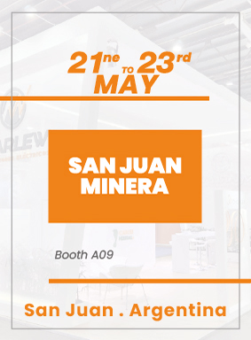
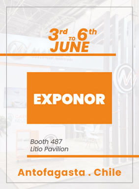
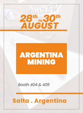
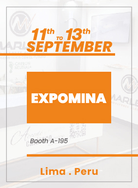
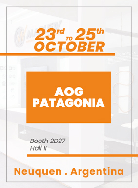
Exhibitions
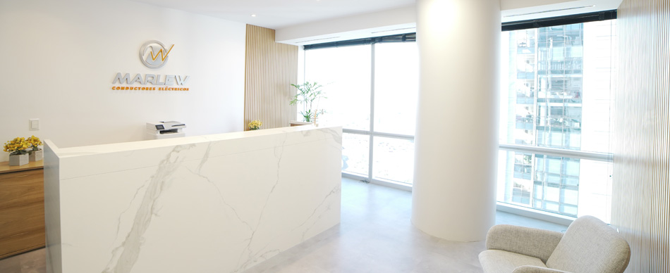
MADERO HARBOUR OFFICES
EZEIZA INDUSTRIAL PLANT