 series UC
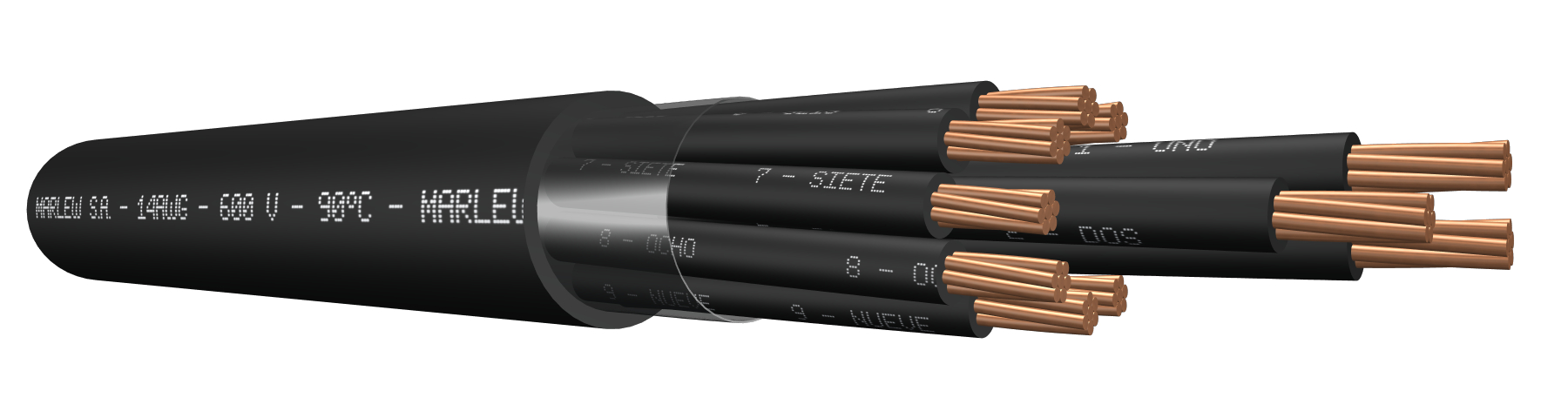
Multiconductor

Control, signalling, measuring and protective equipment; electric controls of industrial installations. Installed in aerial trays, gutters or conduits, under roof or ladder under roof, buried in ducts or directly buried. Manufactured in compliance with the National Electrical Code ANSI/NFPA 70 of the US and the National Electrical Code NOM-001 SEDE, Mexico.
Features
Temperature rating: 90°C (Operating) – 160°C (Short-Circuit)
Temperature rating: 600 Volt A.C.
Construction requirements: As per UL 1277
Conductor requirements: As per ASTM B8
Conductor: Annealed electrolytic copper conductor, class B stranding
Insulation: PVC type THW-2
Sheath: Flame retardant PVC
Fire requirements: As per UL 1685
Outdoors requirements: As per UL 2556 (UV rays)
NEC Code (NFPA 70): Art. 336 TC –Art. 501 classified areas CL1 Div.2 y Cl2 Div.2
Fire-retardant

Mineral oil resistant

UV resistant

Industrial applications

NEC cod

Tray cable
Identification
| Standard | ||
|---|---|---|
| Sheath | Conductors | |
| Multiconductor |  | alphanumeric identification |
Instalation
Constructive variants
The information provided corresponds to the standard version. Upon request, we can supply cables with different alternatives of identification, cable flexibility, or also including additional shield for suitable electromagnetic protection.
DIMENSIONS & WEIGHT
| Cable formation N° Cond. x gauge AWG | External diameter mm | Weight kg/km | Code |
|---|---|---|---|
| 2x14 | 9 | 122 | UC 0214 |
| 3x14 | 9.5 | 148 | UC 0314 |
| 4x14 | 10.4 | 180 | UC 0414 |
| 5x14 | 11.4 | 214 | UC 0514 |
| 7x14 | 12.4 | 277 | UC 0714 |
| 10x14 | 16.3 | 387 | UC 1014 |
| 12x14 | 16.8 | 447 | UC 1214 |
| 14x14 | 18 | 512 | UC 1414 |
| 16x14 | 19 | 575 | UC 1614 |
| 19x14 | 20 | 670 | UC 1914 |
| 21x14 | 22.1 | 784 | UC 2114 |
| 24x14 | 24.1 | 888 | UC 2414 |
| 27x14 | 24.6 | 978 | UC 2714 |
| 30x14 | 25.8 | 1074 | UC 3014 |
| 32x14 | 26.7 | 1141 | UC 3214 |
| 37x14 | 27.8 | 1298 | UC 3714 |
| 48x14 | 31.3 | 1645 | UC 4814 |
| 2x12 | 10 | 161 | UC 0212 |
| 3x12 | 10.6 | 199 | UC 0312 |
| 4x12 | 11.6 | 245 | UC 0412 |
| 5x12 | 12.7 | 292 | UC 0512 |
| 7x12 | 14.6 | 408 | UC 0712 |
| 10x12 | 18.2 | 531 | UC 1012 |
| 12x12 | 18.8 | 618 | UC 1212 |
| 14x12 | 20.1 | 710 | UC 1412 |
| 16x12 | 22.3 | 851 | UC 1612 |
| 19x12 | 23.4 | 990 | UC 1912 |
| 21x12 | 24.7 | 1085 | UC 2112 |
| 24x12 | 26.9 | 1231 | UC 2412 |
| 27x12 | 27.5 | 1361 | UC 2712 |
| 30x12 | 28.9 | 1499 | UC 3012 |
| 32x12 | 30 | 1593 | UC 3212 |
| 37x12 | 31.1 | 1819 | UC 3712 |
| 48x12 | 35.2 | 2317 | UC 4812 |
| 2x10 | 11.2 | 220 | UC 0210 |
| 3x10 | 11.9 | 276 | UC 0310 |
| 4x10 | 13.1 | 343 | UC 0410 |
| 5x10 | 15.1 | 437 | UC 0510 |
| 7x10 | 16.4 | 573 | UC 0710 |
| 10x10 | 20.6 | 752 | UC 1010 |
| 12x10 | 22.2 | 931 | UC 1210 |
| 14x10 | 23.8 | 1070 | UC 1410 |
| 16x10 | 25.1 | 1205 | UC 1610 |
| 19x10 | 26.5 | 1410 | UC 1910 |
| 21x10 | 27.9 | 1548 | UC 2110 |
| 24x10 | 30.5 | 1758 | UC 2410 |
| 27x10 | 31.2 | 1951 | UC 2710 |
| 30x10 | 32.8 | 2152 | UC 3010 |
| 32x10 | 34 | 2289 | UC 3210 |
| 37x10 | 35.4 | 2623 | UC 3710 |
| 48x10 | 40.1 | 3354 | UC 4810 |
ELECTRICAL CHARACTERISTICS
| Calibre AWG | Electrical resistance at 20°C in C.C. (Ohm/km) | Electrical resistance at 90°C in C.A. at 60Hz (Ohm/km) | Current-carrying capacity (1) | ||||||
|---|---|---|---|---|---|---|---|---|---|
| 2x | 4x | 7x | 10x | 19x | 30x | 48x | |||
| 14 | 8.79 | 11.21 | 25 | 20 | 17.5 | 12.5 | 12.5 | 11.3 | 8.8 |
| 12 | 5.54 | 7.06 | 30 | 24 | 21 | 15 | 15 | 13.5 | 10.5 |
| 10 | 3.48 | 4.44 | 40 | 32 | 28 | 20 | 20 | 18 | 14 |
(1) Current-carrying capacity of cables with up to three conductors, installed in ducts or directly buried, up to an ambient temperature of 30ºC, according to chart 310.15 (B)(16) of the NFPA 70. As from four-conductors, we’ve additionally applied the correction factor for more than three conductors from the chart 310.15 (B)(3)(a) of the NFPA70.