 Clad series TKP
Multiconductor Armour (Interlock)
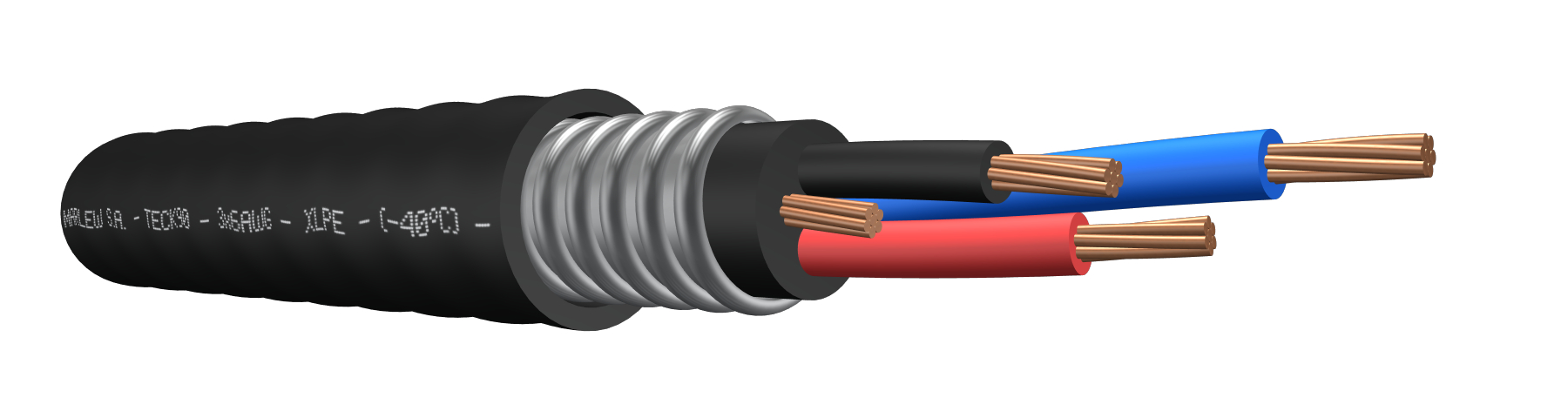


Aluminum tape interlock armour
Power distribution networks in mining, industrial and petrochemical projects. For dry and wet locations, fixed on trays, indoors or outdoors, buried in ducts or directly buried. Suitable for mobile installations at low temperatures Manufactured in compliance with the Canadian Electrical Code CEC
Features
Temperature ratings: 90°C (Operating) – 130°C (Overload) – 250°C (Short-Circuit)
Minimum operating temperature: -40°C
Voltage rating: 1000 Volt A.C.
Construction requirements: CSA 22.2 N°131
Conductor requirements: ASTM B8
Conductor: Annealed electrolytic copper conductor, class B stranding, C o D
Bonding: In all cable formations these cables have a bare copper bonding conductor (PE)
Insulation: XLPE (Cross-Linked Polyethylene)
Inner Sheath: Flame retardant PVC
Armour: Aluminum tape interlock armour
External Sheath: Flame retardant PVC and UV resistant
Fire requirements: As per FT1 (for all gauges) FT4 (for 6AWG and bigger)
Amour: Aluminum interlock style band
Sheath: PVC; fire-retardant; sunlight and hydrocarbon-resistant.
Fire requirements: As per UL 1685
Outdoors requirements: As per CSA 22.2 N° 2556 (UV rays)
Acid gas evolution: CSA 22.2 N° 2556 (Low HCl content)

Flame retardant

HCL < 15%

High flexibility

Hydrocarbon resistant

UV resistant

Impact resistant
Identification
| Standard | ||
|---|---|---|
| Sheath | Conductors | |
| 1 Conductor |  | |
| 2 Conductors | |  |
| 3 Conductors | |   |
| 4 Conductors | | |
Instalation


Constructive variants
The information provided corresponds to the standard version. Alternative interlock armour (made of galvanized steel tape) can be manufactured upon request.
ELECTRICAL CHARACTERISTICS
Resistances, reactance and intensity of admissible currents
| Conductor’s gauge (AWG) | Semi-rigid stranded conductor. Electrical Resistance in D.C. at 20ºC (Ohm/km) | Semi-rigid stranded conductor. Electrical resistance in C.C. at 90°C (Ohm/km) | Inductive reactance at 60Hz (Ohm/Km) | Maximum admissible intensities (6) | ||||||
|---|---|---|---|---|---|---|---|---|---|---|
| 1 Conductor (1) | 1 Conductor (2) | 1 Conductor (3) | Multiconductor (4) | 4 Conductors (5) | ||||||
| 1 Conductor | Multiconductor | 1 Conductor | Multiconductor |  |  |  |  |  | | |
| 14 | 8.62 | 8.79 | 10.99 | 11.21 | -- | -- | -- | 0.132 | 0.141 | 25 |
| 12 | 5.43 | 5.54 | 6.92 | 7.06 | -- | -- | -- | 0.123 | 0.132 | 30 |
| 10 | 3.41 | 3.48 | 4.35 | 4.44 | -- | -- | -- | 0.115 | 0.124 | 40 |
| 8 | 2.14 | 2.18 | 2.73 | 2.78 | -- | -- | -- | 0.108 | 0.117 | 55 |
| 6 | 1.35 | 1.38 | 1.72 | 1.76 | 0.204 | 0.256 | 0.187 | 0.11 | 0.119 | 75 |
| 4 | 0.848 | 0.865 | 1.08 | 1.1 | 0.193 | 0.245 | 0.175 | 0.104 | 0.113 | 95 |
| 2 | 0.534 | 0.545 | 0.681 | 0.695 | 0.18 | 0.232 | 0.163 | 0.098 | 0.107 | 130 |
| 1 | 0.423 | 0.431 | 0.54 | 0.551 | 0.181 | 0.234 | 0.164 | 0.103 | 0.111 | 145 |
| 1/0 | 0.335 | 0.342 | 0.428 | 0.437 | 0.176 | 0.229 | 0.159 | 0.1 | 0.109 | 170 |
| 2/0 | 0.266 | 0.271 | 0.34 | 0.347 | 0.171 | 0.223 | 0.153 | 0.097 | 0.106 | 195 |
| 3/0 | 0.211 | 0.215 | 0.271 | 0.276 | 0.165 | 0.217 | 0.148 | 0.095 | 0.104 | 225 |
| 4/0 | 0.167 | 0.17 | 0.215 | 0.219 | 0.159 | 0.212 | 0.142 | 0.093 | 0.101 | 260 |
| 250 | 0.142 | 0.145 | 0.183 | 0.187 | 0.159 | 0.211 | 0.141 | 0.093 | 0.102 | 290 |
| 300 | 0.118 | 0.12 | 0.153 | 0.156 | 0.155 | 0.207 | 0.137 | 0.092 | -- | 320 |
| 350 | 0.101 | 0.103 | 0.132 | 0.135 | 0.151 | 0.204 | 0.134 | -- | -- | 350 |
| 400 | 0.09 | 0.09 | 0.117 | 0.119 | 0.149 | 0.201 | 0.131 | -- | -- | 380 |
| 450 | 0.0787 | 0.0803 | 0.105 | 0.107 | 0.145 | 0.198 | 0.128 | -- | -- | 405 |
| 500 | 0.0708 | 0.0722 | 0.0954 | 0.0973 | 0.144 | 0.196 | 0.126 | -- | -- | 430 |
| 600 | 0.059 | 0.0602 | 0.0813 | 0.0829 | 0.141 | 0.193 | 0.123 | -- | -- | 430 |
| 750 | 0.0472 | 0.0481 | 0.0678 | 0.0691 | 0.135 | 0.187 | 0.118 | -- | -- | 430 |
| 1000 | 0.0354 | 0.0361 | 0.0549 | 0.056 | 0.132 | 0.184 | 0.114 | -- | -- | 430 |
(1) Three single-conductor cables displayed in flat, in contact with each other. (2) Three single-conductor cables displayed in flat, separated by 1 diameter between each other. (3) Three single-conductor cables displayed in a trefoil in contact with each other. (4) Calculation of Inductive reactance valid for two-conductor, three-conductor and five-conductor cables. (5) Calculation of Inductive reactance valid for four-conductor cables. (6) Current-carrying capacity of cables with up to three conductors, installed in ducts or directly buried, up to an ambient temperature of 30ºC, according to chart 310.15 (B)(16) of the NFPA 70. As from four-conductors, we’ve additionally applied the correction factor for more than three conductors from the chart 310.15 (B)(3)(a) of the NFPA70
DIMENSIONS & WEIGHT
| Cable formation | Diameter below armour mm | Diameter under armour mm | External diameter mm | Weight kg/ km | Code | |
|---|---|---|---|---|---|---|
| Fase conductor | Bonding conductor (1) | |||||
| N° Cond. x gauge AWG/MCM | Gauge AWG | |||||
| 1 x 6 | 8 | 10.8 | 17.7 | 20.7 | 534 | TKP 0106 |
| 1 x 4 | 6 | 12.7 | 19.6 | 22.6 | 698 | TKP 0104 |
| 1 x 2 | 6 | 13.9 | 20.9 | 23.9 | 842 | TKP 0102 |
| 1 x 1 | 4 | 17.0 | 24.1 | 27.1 | 1095 | TKP 0101 |
| 1 x 1/0 | 4 | 18.2 | 25.3 | 28.3 | 1229 | TKP 11/0 |
| 1 x 2/0 | 4 | 19.0 | 26.6 | 29.6 | 1464 | TKP 12/0 |
| 1 x 3/0 | 3 | 20.2 | 27.9 | 30.9 | 1711 | TKP 13/0 |
| 1 x 4/0 | 3 | 21.4 | 29.1 | 32.1 | 1947 | TKP 14/0 |
| 1 x 250 | 2 | 23.9 | 31.7 | 34.7 | 2310 | TKP 1250 |
| 1 x 300 | 2 | 25.1 | 32.9 | 35.9 | 2576 | TKP 1300 |
| 1 x 350 | 1 | 26.4 | 34.2 | 37.2 | 2932 | TKP 1350 |
| 1 x 400 | 1 | 27.6 | 35.5 | 38.5 | 3198 | TKP 1400 |
| 1 x 450 | 1/0 | 30.1 | 38.0 | 41.0 | 3815 | TKP 1450 |
| 1 x 500 | 1/0 | 31.3 | 39.3 | 42.3 | 3854 | TKP 1500 |
| 1 x 600 | 1/0 | 31.3 | 39.3 | 42.3 | 4297 | TKP 1600 |
| 1 x 750 | 2/0 | 35.1 | 43.1 | 46.1 | 5236 | TKP 1750 |
| 1 x 1000 | 2/0 | 39.8 | 48.1 | 51.2 | 6652 | TKP 11000 |
| 2 x 14 | 14 | 10.8 | 17.7 | 20.7 | 395 | TKP 0214 |
| 2 x 12 | 14 | 12.0 | 19.0 | 22.0 | 446 | TKP 0212 |
| 2 x 10 | 12 | 13.3 | 20.2 | 23.2 | 524 | TKP 0210 |
| 2 x 8 | 10 | 15.2 | 22.1 | 25.2 | 663 | TKP 0208 |
| 2 x 6 | 8 | 18.2 | 25.3 | 28.3 | 864 | TKP 0206 |
| 2 x 4 | 8 | 21.4 | 29.1 | 32.1 | 1183 | TKP 0204 |
| 2 x 2 | 6 | 25.1 | 32.9 | 35.9 | 1609 | TKP 0202 |
| 2 x 1 | 6 | 28.8 | 36.8 | 39.8 | 1905 | TKP 0201 |
| 2 x 1/0 | 6 | 30.1 | 38.0 | 41.0 | 2167 | TKP 21/0 |
| 2 x 2/0 | 6 | 32.5 | 40.6 | 43.6 | 2500 | TKP 22/0 |
| 2 x 3/0 | 4 | 35.1 | 43.1 | 46.1 | 2978 | TKP 23/0 |
| 2 x 4/0 | 4 | 38.6 | 46.9 | 49.9 | 3588 | TKP 24/0 |
| 2 x 250 | 4 | 41.1 | 49.5 | 52.5 | 4062 | TKP 2250 |
| 2 x 300 | 4 | 44.9 | 53.3 | 56.3 | 4781 | TKP 2300 |
| 3 x 14 | 14 | 11.4 | 18.3 | 21.3 | 438 | TKP 0314 |
| 3 x 12 | 14 | 12.7 | 19.6 | 22.6 | 503 | TKP 0312 |
| 3 x 10 | 12 | 14.5 | 21.5 | 24.5 | 634 | TKP 0310 |
| 3 x 8 | 10 | 17.0 | 24.1 | 27.1 | 783 | TKP 0308 |
| 3 x 6 | 8 | 20.2 | 27.9 | 30.9 | 1142 | TKP 0306 |
| 3 x 4 | 8 | 23.9 | 31.7 | 34.7 | 1516 | TKP 0304 |
| 3 x 2 | 6 | 26.4 | 34.2 | 37.2 | 1993 | TKP 0302 |
| 3 x 1 | 6 | 30.1 | 38.0 | 41.0 | 2389 | TKP 0301 |
| 3 x 1/0 | 6 | 32.5 | 40.6 | 43.6 | 2786 | TKP 31/0 |
| 3 x 2/0 | 6 | 35.1 | 43.1 | 46.1 | 3255 | TKP 32/0 |
| 3 x 3/0 | 4 | 37.3 | 45.6 | 48.6 | 3997 | TKP 33/0 |
| 3 x 4/0 | 4 | 41.1 | 49.5 | 52.5 | 4726 | TKP 34/0 |
| 3 x 250 | 4 | 46.2 | 54.5 | 57.5 | 5598 | TKP 3250 |
| 4 x 14 | 14 | 12.7 | 19.6 | 22.6 | 494 | TKP 0414 |
| 4 x 12 | 14 | 14.5 | 21.5 | 24.5 | 604 | TKP 0412 |
| 4 x 10 | 12 | 17.0 | 24.1 | 27.1 | 739 | TKP 0410 |
| 4 x 8 | 10 | 18.2 | 25.3 | 28.3 | 910 | TKP 0408 |
| 4 x 6 | 8 | 23.9 | 31.7 | 34.7 | 1430 | TKP 0406 |
| 4 x 4 | 8 | 26.4 | 34.2 | 37.2 | 1812 | TKP 0404 |
| 4 x 2 | 6 | 30.1 | 38.0 | 41.0 | 2440 | TKP 0402 |
| 4 x 1 | 6 | 33.8 | 41.8 | 44.8 | 2932 | TKP 0401 |
| 4 x 1/0 | 6 | 36.0 | 44.4 | 47.4 | 3538 | TKP 41/0 |
| 4 x 2/0 | 6 | 39.6 | 46.9 | 49.9 | 4149 | TKP 42/0 |
| 4 x 3/0 | 4 | 41.1 | 49.5 | 52.5 | 4974 | TKP 43/0 |
| 4 x 4/0 | 4 | 46.2 | 54.5 | 57.5 | 6090 | TKP 44/0 |
(1) For single-conductor cables, the bonding is concentric. For the remaing formations, it is gathered with the phases.