 series VF
Three-conductor shielded
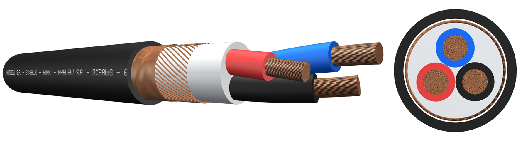
Variable frequency drive motor feed. (VFD) For Alternating Current (60Hz), for single-phase systems (110V), three-phase systems (190/210V) and systems with voltages up to 600V. Installed in aerial trays, gutters or conduits, under roof or ladder under roof, buried in ducts or directly buried.
Features
Temperature ratings: 90°C (Operating) – 130°C (Overload) – 250°C (Short-Circuit)
Voltage rating: 600 Volt A.C.
Construction requirements: As per ICEA S 95-658
Conductor requirements: Serie ASTM B172 up to B174
Conductor: Annealed electrolytic copper - Flexible stranding
Insulation: XLPE (Cross-Linked Polyethylene)
Bedding: PVC
Shield: Conformed by a concentric conductor made of copper wires plus an additional copper tape with adequate overlap and 100% coverage. The shield cross-section is indicated in the electrical characteristics table.
Sheath: Flame retardant PVC, sunlight, and mineral oil resistant
Fire requirements: As per FT1 (UL 1581)
Oils requirements: As per ICEA S 73-532
Outdoors requirements: As per UL 2556 (UV rays)

Electromagnetic interference protection

Flame retardant

UV resistant
Sequentially marked

Industrial applications

Tray cable
Identification
| Standard | ||
|---|---|---|
| Sheath | Conductors | |
| 3 Conductors |  |   |
Instalation

DIMENSIONS & WEIGHT
| Cable formation N° Cond. x gauge AWG | Diameter below shield mm | External diameter mm | Weight kg/km | Code |
|---|---|---|---|---|
| 3 x 14 | 8.8 | 11.6 | 206 | VF 0314 |
| 3 x 12 | 9.9 | 14.1 | 288 | VF 0312 |
| 3 x 10 | 11.2 | 15.5 | 388 | VF 0310 |
| 3 x 8 | 15 | 19.3 | 581 | VF 0308 |
| 3 x 6 | 17.5 | 22.8 | 862 | VF 0306 |
| 3 x 4 | 20.4 | 25.7 | 1172 | VF 0304 |
| 3 x 2 | 23.2 | 28.5 | 1636 | VF 0302 |
| 3 x 1 | 26.5 | 31.8 | 2012 | VF 0301 |
| 3 x 1/0 | 29.1 | 34.4 | 2387 | VF 31/0 |
| 3 x 2/0 | 31.9 | 37.2 | 2892 | VF 32/0 |
| 3 x 3/0 | 35.4 | 40.7 | 3591 | VF 33/0 |
| 3 x 4/0 | 38.6 | 45.4 | 4478 | VF 34/0 |
| 3 x 250 | 43.6 | 50.4 | 5360 | VF 3250 |
| 3 x 300 | 47.5 | 54.3 | 6276 | VF 3300 |
| 3 x 350 | 49.6 | 56.5 | 7049 | VF 3350 |
| 3 x 400 | 52.2 | 59.1 | 7861 | VF 3400 |
ELECTRICAL CHARACTERISTICS
Resistances, reactance and intensity of admissible currents
| Conductor’s gauge (AWG) | Concentric conductor gauge (AWG) | Electrical resistance at 20°C in C.C. Ohm/km | Electrical resistance at 20°C en C.C. Concentric conductor Ohm/km | Electrical resistance at 90°C en C.C. Ohm/km | Electrical resistance at 90°C en C.C. Concentric conductor Ohm/km | Inductive reactance at 60Hz (Ohm/Km) | Intensidad admisible (Ampere) |
|---|---|---|---|---|---|---|---|
 | | ||||||
| 14 | 14 | 8.77 | 8.77 | 11.19 | 11.19 | 0.098 | 25 |
| 12 | 12 | 5.52 | 5.52 | 7.04 | 7.04 | 0.092 | 30 |
| 10 | 10 | 3.48 | 3.48 | 4.43 | 4.43 | 0.086 | 40 |
| 8 | 10 | 2.19 | 3.48 | 2.79 | 4.43 | 0.090 | 55 |
| 6 | 8 | 1.40 | 2.19 | 1.78 | 2.79 | 0.084 | 75 |
| 4 | 8 | 0.880 | 2.19 | 1.12 | 2.79 | 0.080 | 95 |
| 2 | 6 | 0.556 | 1.40 | 0.709 | 1.78 | 0.077 | 130 |
| 1 | 6 | 0.439 | 1.40 | 0.560 | 1.78 | 0.078 | 145 |
| 1/0 | 6 | 0.351 | 1.40 | 0.448 | 1.78 | 0.076 | 170 |
| 2/0 | 6 | 0.279 | 1.40 | 0.358 | 1.78 | 0.074 | 195 |
| 3/0 | 4 | 0.221 | 0.880 | 0.284 | 1.12 | 0.072 | 225 |
| 4/0 | 4 | 0.175 | 0.880 | 0.226 | 1.12 | 0.071 | 260 |
| 250 | 4 | 0.150 | 0.880 | 0.194 | 1.12 | 0.072 | 290 |
| 300 | 3 | 0.125 | 0.699 | 0.163 | 0.893 | 0.071 | 320 |
| 350 | 3 | 0.107 | 0.699 | 0.140 | 0.893 | 0.070 | 350 |
| 400 | 3 | 0.0937 | 0.699 | 0.124 | 0.893 | 0.070 | 380 |
Current-carrying capacity of cables with up to three conductors, installed in ducts or directly buried, up to an ambient temperature of 30ºC, according to chart 310.15 (B)(16) of the NFPA 70.