 Clad series RM-F
Multiconductors Shield (Tape)
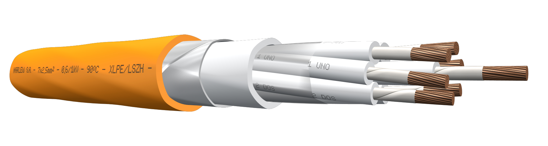


Steel tape armour
Fixed power distribution networks in factories, warehouses, machine rooms, power distribution stations. Control, signalling, measuring and protective equipment, electric controls of home installations. Use in closed environments with a high concentration of people (airports, hospitals, trains, cinemas, shopping centers, tunnels) and in control rooms with electronic equipment sensitive to the exposure of corrosive gases. Installed in aerial trays, gutters or conduits, under roof or ladder under roof, buried in ducts or directly buried. It has additional mechanical protection.
Features
Temperature ratings: 90°C (Operating) – 130°C (Overload) – 250°C (Short-Circuit)
Voltage rating: 600/1000 Volt A.C. – 1200 Volt A.C. (Max) – 1500 Volt D.C.
Construction requirements: IRAM 62266 – IEC 60502-1
Conductor requirements: IRAM NM 280 – IEC 60228
Conductor: Annealed electrolytic copper - Flexible stranding class 5
Insulation: Mica tape + XLPE (Cross-Linked Polyethylene)
Bedding: LSZH-HFFR (Low Smoke Zero Halogen - Halogen Free Flame Retardant)
Armour: Double galvanized steel helical tape
Sheath: LSZH-HFFR (Low Smoke Zero Halogen - Halogen Free Flame Retardant), flame retardant, sunlight, and oil resistant
Fire requirements: As per IEC 60332-3-24
Fire resistance standards: As per IEC 60331-21 (70000 BTU-750°C applied for 90 minutes
Standard for Halogen absence and corrosive gases: IEC 60754-1/2
Smoke transparency requirements: IEC 60754-1/2
Toxicity standard: NES 713 – CEI 20.37
Oils requirements: As per ICEA S 73-532
Outdoors requirements: As per UL 2556 (UV rays)
Water behaviour requirements: Suitable for AD7 (Occasional water submersion)

Fire-retardant

Fire-resistant

Halogen free

Low smoke

Mineral oil resistant

UV resistant
Identification
| Standard | ||
|---|---|---|
| Sheath | Conductors | |
| Multipolar |  |  alphanumeric identification alphanumeric identification |
Instalation


Constructive variants
The information provided corresponds to the standard version. Special design can be manufactured to comply with reinforced circuit integrity, complying with other standards such as IEC 60331-1/2, EN 50200 or BS 6387.
ELECTRICAL CHARACTERISTICS
Resistances, reactance and intensity of admissible currents
| Nominal cross-section sq mm² | Electrical resistance at 20ºC in C.C Ohm/km | Electrical resistance at 90ºC in C.A. Ohm/km | Current-carrying capacity in free air. At 40°C as per IEC 364-5-523. Formations in perforated trays or ladder type. (Ampere) | ||||||
|---|---|---|---|---|---|---|---|---|---|
| 2x | 4x | 7x | 10x | 19x | 30x | 48x | |||
| 1 | 19.5 | 24.86 | -- | -- | -- | -- | -- | -- | -- |
| 1.5 | 13.3 | 16.96 | 23 | 20 | 16.1 | 11.5 | 11.5 | 10.4 | 8.1 |
| 2.5 | 7.98 | 10.18 | 31 | 28 | 21.7 | 15.5 | 15.5 | 14.0 | 10.9 |
| 4 | 4.95 | 6.31 | 43 | 36 | 30.1 | 21.5 | 21.5 | 19.4 | -- |
As from seven-conductors, we’ve additionally applied the correction factor for more than three conductors the chart 310.15 (B)(3)(a) of the NFPA70.
DIMENSIONS & WEIGHT
| Cable Formation, N° Cond. x cross-section (mm²) | Diameter below armour mm | External diameter mm | Weight kg/km | Code |
|---|---|---|---|---|
| 10 x 1 | 14.7 | 18.5 | 449 | RM 1010 F |
| 12 x 1 | 15.1 | 18.9 | 484 | RM 1210 F |
| 14 x 1 | 16.3 | 20.1 | 540 | RM 1410 F |
| 19 x 1 | 18.2 | 22.0 | 654 | RM 1910 F |
| 24 x 1 | 21.1 | 24.9 | 787 | RM 2410 F |
| 30 x 1 | 22.7 | 26.5 | 908 | RM 3010 F |
| 37 x 1 | 24.6 | 28.4 | 1056 | RM 3710 F |
| 48 x 1 | 28.0 | 31.8 | 1293 | RM 4810 F |
| 5 x 1.5 | 12.0 | 15.8 | 381 | RM 0515 F |
| 7 x 1.5 | 12.7 | 16.5 | 395 | RM 0715 F |
| 10 x 1.5 | 15.8 | 19.6 | 512 | RM 1015 F |
| 12 x 1.5 | 16.4 | 20.2 | 566 | RM 1215 F |
| 14 x 1.5 | 17.6 | 21.4 | 626 | RM 1415 F |
| 19 x 1.5 | 19.7 | 23.5 | 768 | RM 1915 F |
| 24 x 1.5 | 22.9 | 26.7 | 931 | RM 2415 F |
| 30 x 1.5 | 24.6 | 28.4 | 1079 | RM 3015 F |
| 37 x 1.5 | 26.7 | 30.5 | 1264 | RM 3715 F |
| 48 x 1.5 | 30.4 | 34.4 | 1906 | RM 4815 F |
| 3 x 2.5 | 12.0 | 15.8 | 389 | RM 0325 F |
| 4 x 2.5 | 12.0 | 15.8 | 395 | RM 0425 F |
| 5 x 2.5 | 12.7 | 16.5 | 437 | RM 0525 F |
| 7 x 2.5 | 14.0 | 17.8 | 484 | RM 0725 F |
| 10 x 2.5 | 17.6 | 21.4 | 642 | RM 1025 F |
| 12 x 2.5 | 18.2 | 22.0 | 712 | RM 1225 F |
| 14 x 2.5 | 19.6 | 23.4 | 796 | RM 1425 F |
| 19 x 2.5 | 21.9 | 25.7 | 986 | RM 1925 F |
| 24 x 2.5 | 25.5 | 29.3 | 1204 | RM 2425 F |
| 30 x 2.5 | 27.5 | 31.3 | 1417 | RM 3025 F |
| 37 x 2.5 | 29.9 | 33.7 | 1677 | RM 3725 F |
| 48 x 2.5 | 34.4 | 38.6 | 2528 | RM 4825 F |
| 2 x 4 | 12.0 | 15.8 | 398 | RM 0240 F |
| 3 x 4 | 12.0 | 15.8 | 416 | RM 0340 F |
| 4 x 4 | 12.8 | 16.6 | 465 | RM 0440 F |
| 5 x 4 | 14.0 | 17.8 | 541 | RM 0540 F |
| 7 x 4 | 15.5 | 19.3 | 612 | RM 0740 F |
| 10 x 4 | 19.5 | 23.3 | 817 | RM 1040 F |
| 12 x 4 | 20.2 | 24.0 | 919 | RM 1240 F |
| 14 x 4 | 21.8 | 25.6 | 1035 | RM 1440 F |
| 19 x 4 | 24.4 | 28.2 | 1304 | RM 1940 F |
| 24 x 4 | 28.5 | 32.3 | 1605 | RM 2440 F |
| 30 x 4 | 30.7 | 34.7 | 2258 | RM 3040 F |
| 37 x 4 | 33.8 | 38.0 | 2717 | RM 3740 F |