 series PY
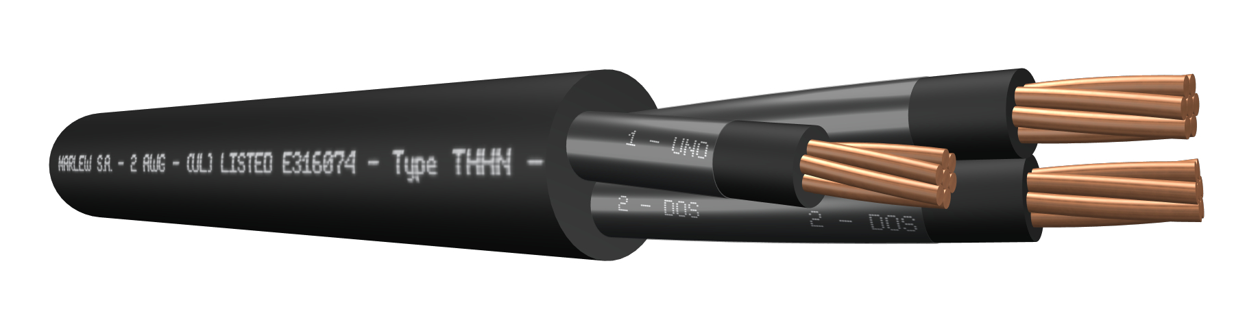
Single and multiconductor


Fixed power distribution networks in factories, warehouses, machine rooms, power distribution stations. Installed in aerial trays, gutters or conduits, under roof or ladder under roof, buried in ducts or directly buried. Manufactured in compliance with the National Electrical Code ANSI/NFPA 70 of the US and the National Electrical Code NOM-001 SEDE, Mexico.
Features
Temperature ratings: 90°C (Operating) – 160°C (Short-Circuit)
Voltage rating: 600 Volt A.C.
Construction requirements: UL 1277
Conductor requirements: ASTM B8
Conductor: Annealed electrolytic copper conductor, class B stranding
Primary insulation: Special PVC Compound
Secondary insulation: THHN (Nylon)
Sheath: Flame retardant PVC
Fire requirements: As per UL 1685
Outdoors requirements: As per UL 2556 (UV rays)
NEC Code (NFPA 70): Art. 336 TC –Art. 501 classified areas CL1 Div.2 y Cl2 Div.2

Fire-retardant

Mineral oil resistant

UV resistant

Industrial applications

Tray cable

Wet locations
Identification
| Standard | ||
|---|---|---|
| Sheath | Conductors | |
| 1 to 5 conductors |  | alphanumeric identification |
Instalation


ELECTRICAL CHARACTERISTICS
| Conductor’s gauge (AWG) | Semi-rigid stranded conductor. Electrical resistance in D.C. at 20ºC (Ohm/km) | Semi-rigid stranded conductor. Electrical resistance in C.C. at 90°C (Ohm/km) | Inductive reactance at 60Hz (Ohm/Km) | Maximum admissible intensities (6) | ||||||
|---|---|---|---|---|---|---|---|---|---|---|
| 1 Conductor (1) | 1 Conductor (2) | 1 Conductor (3) | Multiconductor (4) | 4 Conductors (5) | ||||||
| 1 Conductor | Multiconductor | 1 Conductor | Multiconductor |  |  |  |  |  | | |
| 14 | 8.62 | 8.79 | 10.99 | 11.21 | 0.166 | 0.218 | 0.149 | 0.104 | 0.113 | 25 |
| 12 | 5.43 | 5.54 | 6.92 | 7.06 | 0.155 | 0.208 | 0.138 | 0.099 | 0.107 | 30 |
| 10 | 3.41 | 3.48 | 4.35 | 4.43 | 0.149 | 0.201 | 0.131 | 0.099 | 0.107 | 40 |
| 8 | 2.14 | 2.19 | 2.73 | 2.79 | 0.147 | 0.199 | 0.129 | 0.103 | 0.112 | 55 |
| 6 | 1.35 | 1.37 | 1.72 | 1.75 | 0.138 | 0.19 | 0.12 | 0.098 | 0.107 | 75 |
| 4 | 0.848 | 0.865 | 1.08 | 1.1 | 0.134 | 0.187 | 0.117 | 0.099 | 0.108 | 95 |
| 2 | 0.534 | 0.544 | 0.681 | 0.694 | 0.127 | 0.179 | 0.11 | 0.094 | 0.103 | 130 |
| 1 | 0.423 | 0.431 | 0.54 | 0.551 | 0.131 | 0.183 | 0.113 | 0.096 | 0.105 | 145 |
(1) Three single-conductor cables displayed in flat, in contact with each other. (2) Three single-conductor cables displayed in flat, separated by 1 diameter between each other. (3) Three single-conductor cables displayed in a trefoil in contact with each other. (4) Calculation of Inductive reactance valid for two-conductor, three-conductor and five-conductor cables. (5) Calculation of Inductive reactance valid for four-conductor cables. (6) Current-carrying capacity of cables with up to three conductors, installed in ducts or directly buried, up to an ambient temperature of 30ºC, according to chart 310.15 (B)(16) of the NFPA 70. As from four-conductors, we’ve additionally applied the correction factor for more than three conductors from the chart 310.15 (B)(3)(a) of the NFPA70.
DIMENSIONS & WEIGHT
| Cable Formation N° Cond. x gauge AWG | External diameter mm | Weight kg/km | Code |
|---|---|---|---|
| 1 x 14 | 5.1 | 45 | PY 0114 |
| 1 x 12 | 5.6 | 60 | PY 0112 |
| 1 x 10 | 6.5 | 86 | PY 0110 |
| 1 x 8 | 7.9 | 129 | PY 0108 |
| 1 x 6 | 8.8 | 183 | PY 0106 |
| 1 x 4 | 10.7 | 281 | PY 0104 |
| 1 x 2 | 12.2 | 409 | PY 0102 |
| 1 x 1 | 14.5 | 534 | PY 0101 |
| 2 x 14 | 8.0 | 102 | PY 0214 |
| 2 x 12 | 8.9 | 138 | PY 0212 |
| 2 x 10 | 10.7 | 206 | PY 0210 |
| 2 x 8 | 14.2 | 347 | PY 0208 |
| 2 x 6 | 16.1 | 485 | PY 0206 |
| 2 x 4 | 22.4 | 875 | PY 0204 |
| 2 x 2 | 26.1 | 1257 | PY 0202 |
| 2 x 1 | 29.3 | 1564 | PY 0201 |
| 3 x 14 | 8.4 | 125 | PY 0314 |
| 3 x 12 | 9.5 | 173 | PY 0312 |
| 3 x 10 | 11.3 | 260 | PY 0310 |
| 3 x 8 | 15.1 | 434 | PY 0308 |
| 3 x 6 | 17.2 | 616 | PY 0306 |
| 3 x 4 | 24.5 | 1130 | PY 0304 |
| 3 x 2 | 27.7 | 1589 | PY 0302 |
| 3 x 1 | 31.3 | 1977 | PY 0301 |
| 4 x 14 | 9.2 | 153 | PY 0414 |
| 4 x 12 | 10.3 | 213 | PY 0412 |
| 4 x 10 | 12.4 | 323 | PY 0410 |
| 4 x 8 | 16.5 | 537 | PY 0408 |
| 4 x 6 | 18.9 | 770 | PY 0406 |
| 4 x 4 | 26.6 | 1391 | PY 0404 |
| 4 x 2 | 30.3 | 1975 | PY 0402 |
| 4 x 1 | 34.1 | 2461 | PY 0401 |
| 5 x 14 | 9.2 | 174 | PY 0514 |
| 5 x 12 | 10.3 | 247 | PY 0512 |
| 5 x 10 | 12.4 | 376 | PY 0510 |
| 5 x 8 | 16.5 | 623 | PY 0508 |
| 5 x 6 | 18.9 | 902 | PY 0506 |
| 5 x 4 | 26.6 | 1603 | PY 0504 |
| 5 x 2 | 30.3 | 2300 | PY 0502 |
| 5 x 1 | 34.1 | 2869 | PY 0501 |