 Block series ME-W
Multiconductor Shield (Copper Tape)
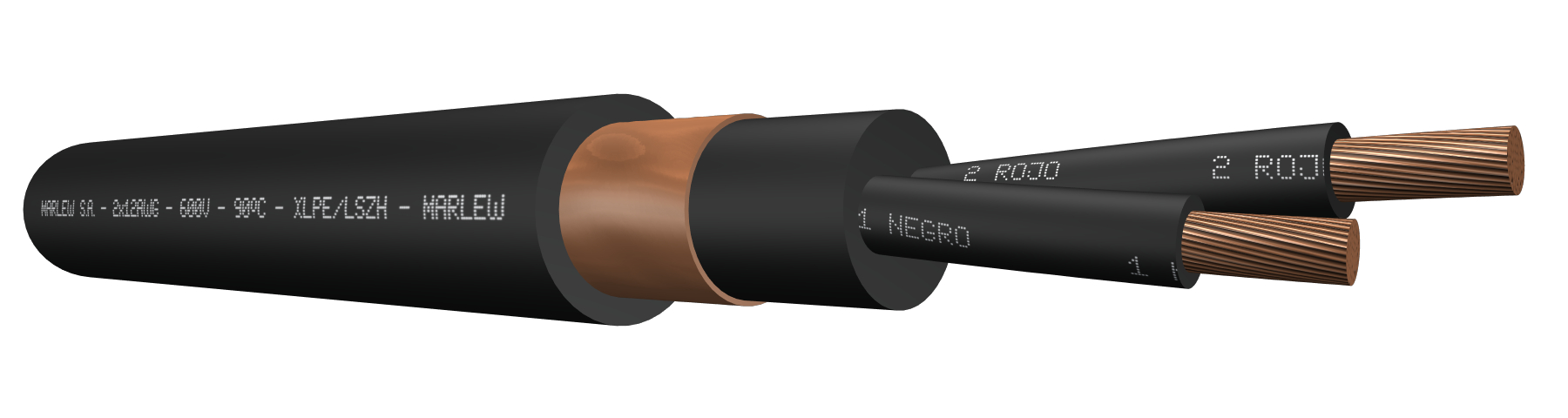

Copper tape shield
Control, signalling, measuring and protective equipment, electric controls of home installations. Use in closed environments with a high concentration of people (airports, hospitals, trains, cinemas, shopping centers, tunnels) and in control rooms with electronic equipment sensitive to the exposure of corrosive gases. Installed in conduits, trays, cable ladders, in direct open air or indoors, buried in a trench or in ducts. It provides additional electromagnetic protection.
Features
Temperature rating: 90ºC (operating),130ºC (overload) and 250ºC (short circuit)
Voltage rating: 600 AC
Construction requirements: As per ICEA S 73-532
Conductor requirements: As per ASTM B174
Conductor: Annealed electrolytic copper; flexible
Insulation: XLPE (Cross-linked polyethylene)
Shield: Annealed copper tape helical wrap with 100% coverage and overlap
Sheath: LSZH-HFFR (Low Smoke Zero Halogen - Halogen Free Flame Retardant), fire-retardant sunlight and oils resistant
Fire requirements: As per ICEA T 30-520
Standard for halogen absence and corrosive gases: As per IEC 60754-1/2
Smoke transparency requirements: As per IEC 61034-1/2
Toxicity standard: As per NES 713 – CEI 20.37
Olis requirements: As per ICEA S 73-532
Outdoors requirements: As per UL 2556 (UV rays)
Water behaviour requirements: Suitable AD7 (Occasional water submersion)
Electromagnetic interference protection
Fire-retardant

Halogen free

Low smoke

Mineral oil resistant

UV resistant
Identification
| Standard | ||
|---|---|---|
| Sheath | Conductors | |
| Multiconductor |  | Method 3 Table E-2 |
Instalation
ELECTRICAL CHARACTERISTICS
Resistances and intensity of admissible currents
| Gauge AWG | Electrical resistance at 20°C in C.C. (Ohm/km) | Electrical resistance at 75°C in AC. a 60Hz (Ohm/km) | Current-carrying capacity (1) | |||||
|---|---|---|---|---|---|---|---|---|
| 2x | 4x | 7x | 10x | 19x | 30x | |||
| 16 | 13.99 | 17.84 | 18 | 14.4 | 12.6 | 9 | 9 | 8.1 |
| 14 | 8.77 | 11.18 | 25 | 20 | 17.5 | 12.5 | 12.5 | 11.3 |
| 12 | 5.52 | 7.04 | 30 | 24 | 21 | 15 | 15 | 13.5 |
| 10 | 3.48 | 4.44 | 40 | 32 | 28 | 20 | 20 | 18 |
(1) Current-carrying capacity of cables with up to three conductors, installed in ducts or directly buried, up to an ambient temperature of 30ºC, according to chart 310.15 (B)(16) of the NFPA 70. As from four-conductors, we’ve additionally applied the correction factor for more than three conductors from the chart 310.15 (B)(3)(a) of the NFPA70.
DIMENSIONS & WEIGHT
| Cable Formation N° Cond. x gauge AWG | Diameter below shield mm | External diameter mm | Weight kg/km | Code |
|---|---|---|---|---|
| 5x18 | 8.2 | 10.9 | 177 | ME 0518 W |
| 7x18 | 8.9 | 11.6 | 207 | ME 0718 W |
| 10x18 | 10.6 | 14.0 | 280 | ME 1018 W |
| 12x18 | 11.5 | 14.9 | 314 | ME 1218 W |
| 14x18 | 12.3 | 15.6 | 347 | ME 1418 W |
| 19x18 | 14.4 | 17.8 | 443 | ME 1918 W |
| 24x18 | 15.9 | 19.3 | 521 | ME 2418 W |
| 30x18 | 17.6 | 22.0 | 662 | ME 3018 W |
| 3x16 | 7.4 | 10.1 | 158 | ME 0316 W |
| 4x16 | 8.2 | 10.8 | 182 | ME 0416 W |
| 5x16 | 8.9 | 11.6 | 209 | ME 0516 W |
| 7x16 | 9.7 | 12.3 | 240 | ME 0716 W |
| 10x16 | 11.6 | 14.9 | 334 | ME 1016 W |
| 12x16 | 12.9 | 16.3 | 393 | ME 1216 W |
| 14x16 | 13.8 | 17.2 | 436 | ME 1416 W |
| 19x16 | 15.7 | 19.1 | 540 | ME 1916 W |
| 24x16 | 17.4 | 20.8 | 640 | ME 2416 W |
| 30x16 | 19.2 | 23.7 | 827 | ME 3016 W |
| 2x14 | 8.3 | 11.0 | 185 | ME 0214 W |
| 3x14 | 8.8 | 11.5 | 210 | ME 0314 W |
| 4x14 | 9.7 | 12.3 | 237 | ME 0414 W |
| 5x14 | 10.7 | 14.0 | 301 | ME 0514 W |
| 7x14 | 11.7 | 15.0 | 360 | ME 0714 W |
| 10x14 | 14.3 | 17.7 | 473 | ME 1014 W |
| 12x14 | 15.5 | 18.9 | 539 | ME 1214 W |
| 14x14 | 16.6 | 19.9 | 603 | ME 1414 W |
| 19x14 | 19.0 | 23.3 | 814 | ME 1914 W |
| 24x14 | 21.6 | 26.0 | 1020 | ME 2414 W |
| 30x14 | 23.8 | 28.3 | 1206 | ME 3014 W |
| 2x12 | 9.2 | 11.9 | 227 | ME 0212 W |
| 3x12 | 9.9 | 12.5 | 256 | ME 0312 W |
| 4x12 | 10.9 | 14.2 | 328 | ME 0412 W |
| 5x12 | 11.9 | 15.3 | 384 | ME 0512 W |
| 7x12 | 13.5 | 16.8 | 484 | ME 0712 W |
| 10x12 | 16.1 | 19.4 | 615 | ME 1012 W |
| 12x12 | 18.6 | 23.0 | 850 | ME 1212 W |
| 19x12 | 21.9 | 26.3 | 1126 | ME 1912 W |
| 24x12 | 24.2 | 28.7 | 1351 | ME 2412 W |
| 30x12 | 26.8 | 31.2 | 1613 | ME 3012 W |
| 2x10 | 10.5 | 13.8 | 308 | ME 0210 W |
| 3x10 | 11.2 | 14.5 | 362 | ME 0310 W |
| 4x10 | 12.3 | 15.7 | 431 | ME 0410 W |
| 5x10 | 14.0 | 17.3 | 528 | ME 0510 W |
| 7x10 | 15.3 | 18.7 | 651 | ME 0710 W |
| 10x10 | 21.8 | 26.2 | 1206 | ME 1010 W |
| 19x10 | 24.9 | 29.4 | 1539 | ME 1910 W |
| 24x10 | 27.7 | 32.1 | 1864 | ME 2410 W |
| 30x10 | 30.7 | 35.1 | 2247 | ME 3010 W |