 Block series CY-W
Multiconductor Shield (Copper Tape)
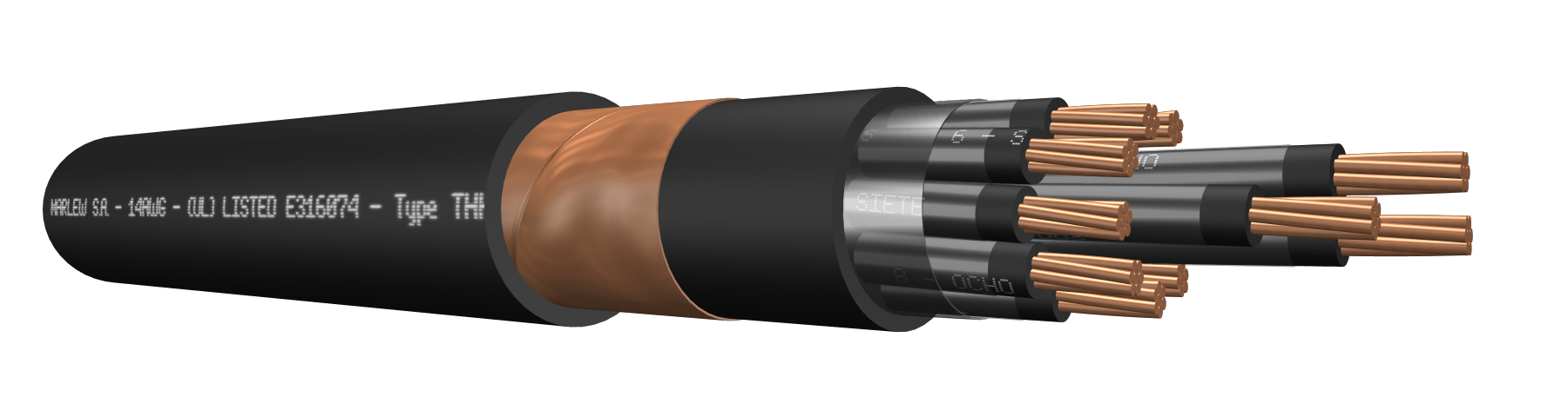


Copper tape shield
Control, signalling, measuring and protective equipment; electric controls of industrial installations. Installed in aerial trays, gutters or conduits, under roof or ladder under roof, buried in ducts or directly buried. It provides additional electromagnetic protection. Manufactured in compliance with the National Electrical Code ANSI/NFPA 70 of the US and the National Electrical Code NOM-001 SEDE, Mexico.
Features
Temperature rating: 90ºC (operating), 160ºC (short circuit)
Voltage rating: 600V AC
Construction requirements: As per UL 1277
Conductor requirements: As per ASTM B8
Conductor: Annealed electrolytic copper; class B
Primary insulation: Special PVC compound
Secondary insulation: THHN (Nylon)
Shield: Annealed copper tape helical wrap with 100% coverage and overlap
Sheath: PVC, fire-retardant
Fire requirements: As per UL 1685
Test requirements: As per UL 2556 (UV rays)
NEC code (NFPA 70): Art 336 - Art 501 classified areas Cl 1 Div 2 and Cl 2 Div 2
Electromagnetic interference protection
Fire-retardant

Mineral oil resistant

UV resistant

Industrial applications

Wet locations
Identification
| Standard | ||
|---|---|---|
| Sheath | Conductors | |
| Multiconductor |  | alphanumeric identification |
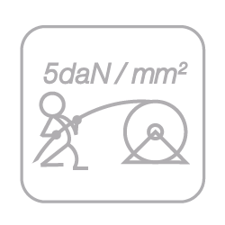
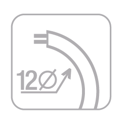
Instalation
ELECTRICAL CHARACTERISTICS
Resistances and intensity of admissible currents
| Gauge AWG | Electrical resistance at 20°C in C.C. (Ohm/km) | Electrical resistance at 90°C in C.A. at 60Hz (Ohm/km) | Current-carrying capacity (1) | ||||||
|---|---|---|---|---|---|---|---|---|---|
| 2x | 4x | 7x | 10x | 19x | 30x | 48x | |||
| 14 | 8.79 | 11.21 | 25 | 20 | 17.5 | 12.5 | 12.5 | 11.3 | 8.8 |
| 12 | 5.54 | 7.06 | 30 | 24 | 21 | 15 | 15 | 13.5 | 10.5 |
| 10 | 3.48 | 4.44 | 40 | 32 | 28 | 20 | 20 | 18 | 14 |
(1) Current-carrying capacity of cables with up to three conductors, installed in ducts or directly buried, up to an ambient temperature of 30ºC, according to chart 310.15 (B)(16) of the NFPA 70. As from four-conductors, we’ve additionally applied the correction factor for more than three conductors from the chart 310.15 (B)(3)(a) of the NFPA70.
DIMENSIONS & WEIGHT
| Cable Formation N° Cond. x gauge AWG | Diameter below shield mm | External diameter mm | Weight kg/km | Code |
|---|---|---|---|---|
| 2 x 14 | 7.3 | 9.9 | 155 | CY 0214 W |
| 3 x 14 | 7.7 | 10.3 | 181 | CY 0314 W |
| 4 x 14 | 8.4 | 11.1 | 213 | CY 0414 W |
| 5 x 14 | 9.2 | 11.8 | 247 | CY 0514 W |
| 7 x 14 | 10.1 | 12.7 | 307 | CY 0714 W |
| 10 x 14 | 12.8 | 16.1 | 425 | CY 1014 W |
| 12 x 14 | 13.2 | 16.6 | 479 | CY 1214 W |
| 14 x 14 | 14.2 | 17.6 | 541 | CY 1414 W |
| 19 x 14 | 15.9 | 19.3 | 687 | CY 1914 W |
| 24 x 14 | 18.4 | 22.8 | 895 | CY 2414 W |
| 30 x 14 | 20.6 | 25.0 | 1118 | CY 3014 W |
| 37 x 14 | 22.2 | 26.7 | 1323 | CY 3714 W |
| 48 x 14 | 25.2 | 29.7 | 1647 | CY 4814 W |
| 2 x 12 | 8.2 | 10.8 | 198 | CY 0212 W |
| 3 x 12 | 8.7 | 11.4 | 236 | CY 0312 W |
| 4 x 12 | 9.6 | 12.2 | 282 | CY 0412 W |
| 5 x 12 | 10.5 | 13.9 | 353 | CY 0512 W |
| 7 x 12 | 11.5 | 14.9 | 441 | CY 0712 W |
| 10 x 12 | 14.7 | 18.0 | 574 | CY 1012 W |
| 12 x 12 | 15.2 | 18.5 | 655 | CY 1212 W |
| 14 x 12 | 16.3 | 19.7 | 744 | CY 1412 W |
| 19 x 12 | 18.3 | 22.7 | 1008 | CY 1912 W |
| 24 x 12 | 22.0 | 26.4 | 1298 | CY 2412 W |
| 30 x 12 | 23.6 | 28.1 | 1549 | CY 3012 W |
| 37 x 12 | 25.6 | 30.1 | 1851 | CY 3712 W |
| 48 x 12 | 29.1 | 33.5 | 2321 | CY 4812 W |
| 2 x 10 | 10.0 | 12.6 | 276 | CY 0210 W |
| 3 x 10 | 10.6 | 14.0 | 358 | CY 0310 W |
| 4 x 10 | 11.7 | 15.1 | 429 | CY 0410 W |
| 5 x 10 | 12.9 | 16.2 | 504 | CY 0510 W |
| 7 x 10 | 14.1 | 17.5 | 641 | CY 0710 W |
| 10 x 10 | 18.0 | 22.4 | 889 | CY 1010 W |
| 12 x 10 | 18.7 | 23.0 | 1016 | CY 1210 W |
| 14 x 10 | 20.9 | 25.3 | 1212 | CY 1410 W |
| 19 x 10 | 23.3 | 27.8 | 1554 | CY 1910 W |
| 24 x 10 | 27.1 | 31.5 | 1917 | CY 2410 W |
| 30 x 10 | 29.2 | 33.7 | 2308 | CY 3010 W |
| 37 x 10 | 31.7 | 36.1 | 2775 | CY 3710 W |
| 48 x 10 | 36.1 | 40.5 | 3505 | CY 4810 W |