 Clad series MA-H
Multiconductor Armour (SWA)
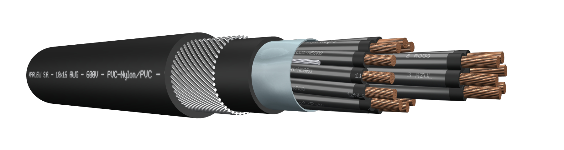

Aluminium/polyester tape helical wrap + Steel tape armour
Control, signalling, measuring and protective equipment; electric controls of industrial installations. Installed in aerial trays, gutters or conduits, under roof or ladder under roof, buried in ducts or directly buried. It counts with additional electromagnetic and mechanical protection.
Features
Temperature rating: 90ºC (operating), 160°C (short circuit)
Voltage rating: 600V AC
Construction requirements: As per ICEA S 73-532
Conductor requirements: As per ASTM B174
Conductor: Annealed electrolytic copper; flexible
Primary insulation: Special PVC
Secondary insulation: Nylon
Shield: Aluminium/polyester tape helical wrap with 100% coverage and overlap. Drain wire in contact with the aluminium side of the tape. Drain consists of a 7-wire tinned copper thread
Inner sheath: PVC
Armour: Galvanized steel wire armour
Sheath: PVC fire-retardant; sunlight and mineral-oil resistant.
Fire requirements: As per ICEA T 30-520
Oils requirements: As per ICEA S 73-532
Outdoors requirements: As per UL 2556 (UV rays)

Electromagnetic interference protection

Fire-retardant

Mineral oil resistant

UV resistant

Industrial applications
Direct burial
Identification
| Standard | ||
|---|---|---|
| Sheath | Conductors | |
| Multiconductor |  | Method 3 Table E-2 |
Instalation

DIMENSIONS & WEIGHT
| Cable formation N° Cond. x gauge AWG | Diameter under armour mm | External diameter mm | Weight kg/km | Code |
|---|---|---|---|---|
| 2 x 16 | 7.5 | 11.7 | 261 | MA 0216 H |
| 3 x 16 | 7.9 | 12.1 | 287 | MA 0316 H |
| 4 x 16 | 8.6 | 12.7 | 320 | MA 0416 H |
| 5 x 16 | 9.3 | 14.2 | 377 | MA 0516 H |
| 7 x 16 | 10 | 15.8 | 541 | MA 0716 H |
| 10 x 16 | 12.3 | 18.1 | 671 | MA 1016 H |
| 12 x 16 | 12.7 | 18.4 | 716 | MA 1216 H |
| 14 x 16 | 14.3 | 20.1 | 828 | MA 1416 H |
| 16 x 16 | 15 | 21.5 | 1013 | MA 1616 H |
| 19 x 16 | 15.8 | 22.3 | 1095 | MA 1916 H |
| 21 x 16 | 16.6 | 23.1 | 1164 | MA 2116 H |
| 24 x 16 | 18 | 24.5 | 1275 | MA 2416 H |
| 27 x 16 | 18.4 | 24.9 | 1339 | MA 2716 H |
| 30 x 16 | 19.3 | 25.8 | 1427 | MA 3016 H |
| 32 x 16 | 20 | 26.5 | 1491 | MA 3216 H |
| 37 x 16 | 20.8 | 27.3 | 1606 | MA 3716 H |
| 48 x 16 | 24.4 | 30.9 | 1991 | MA 4816 H |
| 2 x 14 | 8.2 | 12.3 | 294 | MA 0214 H |
| 3 x 14 | 8.6 | 12.8 | 329 | MA 0314 H |
| 4 x 14 | 9.4 | 14.3 | 395 | MA 0414 H |
| 5 x 14 | 10.2 | 16 | 553 | MA 0514 H |
| 7 x 14 | 11 | 16.8 | 632 | MA 0714 H |
| 10 x 14 | 14.3 | 20.1 | 843 | MA 1014 H |
| 12 x 14 | 14.8 | 20.6 | 906 | MA 1214 H |
| 14 x 14 | 15.8 | 22.3 | 1123 | MA 1414 H |
| 16 x 14 | 16.6 | 23.1 | 1206 | MA 1614 H |
| 19 x 14 | 17.4 | 23.9 | 1316 | MA 1914 H |
| 21 x 14 | 18.4 | 24.9 | 1406 | MA 2114 H |
| 24 x 14 | 20 | 26.5 | 1549 | MA 2414 H |
| 27 x 14 | 20.4 | 26.9 | 1638 | MA 2714 H |
| 30 x 14 | 22.5 | 29 | 1843 | MA 3014 H |
| 32 x 14 | 23.3 | 29.8 | 1929 | MA 3214 H |
| 37 x 14 | 24.1 | 30.6 | 2090 | MA 3714 H |
| 48 x 14 | 27.1 | 34.7 | 2778 | MA 4814 H |
| 2 x 12 | 9.1 | 13.3 | 342 | MA 0212 H |
| 3 x 12 | 9.7 | 14.6 | 414 | MA 0312 H |
| 4 x 12 | 10.5 | 16.3 | 589 | MA 0412 H |
| 5 x 12 | 11.4 | 17.2 | 658 | MA 0512 H |
| 7 x 12 | 12.4 | 18.2 | 764 | MA 0712 H |
| 10 x 12 | 16.2 | 22.7 | 1162 | MA 1012 H |
| 12 x 12 | 16.7 | 23.1 | 1254 | MA 1212 H |
| 14 x 12 | 17.8 | 24.3 | 1377 | MA 1412 H |
| 16 x 12 | 18.8 | 25.3 | 1490 | MA 1612 H |
| 19 x 12 | 19.8 | 26.3 | 1643 | MA 1912 H |
| 21 x 12 | 21.9 | 28.4 | 1849 | MA 2112 H |
| 24 x 12 | 23.8 | 30.3 | 2044 | MA 2412 H |
| 27 x 12 | 24.3 | 30.8 | 2172 | MA 2712 H |
| 30 x 12 | 25.5 | 33.1 | 2609 | MA 3012 H |
| 32 x 12 | 26.4 | 34 | 2731 | MA 3212 H |
| 37 x 12 | 27.4 | 35 | 2968 | MA 3712 H |
| 48 x 12 | 30.9 | 38.5 | 3545 | MA 4812 H |
| 2 x 10 | 10.9 | 16.7 | 575 | MA 0210 H |
| 3 x 10 | 11.5 | 17.3 | 655 | MA 0310 H |
| 4 x 10 | 12.6 | 18.4 | 751 | MA 0410 H |
| 5 x 10 | 14.6 | 20.4 | 897 | MA 0510 H |
| 7 x 10 | 15.8 | 22.3 | 1189 | MA 0710 H |
| 10 x 10 | 19.6 | 26.1 | 1527 | MA 1010 H |
| 12 x 10 | 20.2 | 26.7 | 1667 | MA 1210 H |
| 14 x 10 | 22.7 | 29.2 | 1936 | MA 1410 H |
| 16 x 10 | 23.9 | 30.4 | 2105 | MA 1610 H |
| 19 x 10 | 25.2 | 32.8 | 2610 | MA 1910 H |
| 21 x 10 | 26.6 | 34.1 | 2798 | MA 2110 H |
| 24 x 10 | 28.9 | 36.5 | 3099 | MA 2410 H |
| 27 x 10 | 29.6 | 37.2 | 3301 | MA 2710 H |
| 30 x 10 | 31.1 | 38.7 | 3552 | MA 3010 H |
| 32 x 10 | 32.3 | 39.9 | 3797 | MA 3210 H |
| 37 x 10 | 33.5 | 41.1 | 4156 | MA 3710 H |
| 48 x 10 | 37.9 | 47.3 | 5512 | MA 4810 H |
ELECTRICAL CHARACTERISTICS
Resistances and intensity of admissible currents
| Gauge AWG | Electrical resistance at 20°C in C.C. (Ohm/km) | Electrical resistance at 90°C in C.A. at 60Hz (Ohm/km) | Current-carrying capacity (1) | |||||
|---|---|---|---|---|---|---|---|---|
| 2x | 4x | 7x | 10x | 19x | 30x | |||
| 16 | 13.99 | 17.84 | 18 | 14.4 | 12.6 | 9 | 9 | 8.1 |
| 14 | 8.77 | 11.18 | 25 | 20 | 17.5 | 12.5 | 12.5 | 11.3 |
| 12 | 5.52 | 7.04 | 30 | 24 | 21 | 15 | 15 | 13.5 |
| 10 | 3.48 | 4.44 | 40 | 32 | 28 | 20 | 20 | 18 |
(1) Current-carrying capacity of cables with up to three conductors, installed in ducts or directly buried, up to an ambient temperature of 30ºC, according to chart 310.15 (B)(16) of the NFPA 70. As from four-conductors, we’ve additionally applied the correction factor for more than three conductors from the chart 310.15 (B)(3)(a) of the NFPA70.