 Clad series GV-F
Single and multiconductor Armours (Tape)


Corrugated copper shielding + Steel tape armour
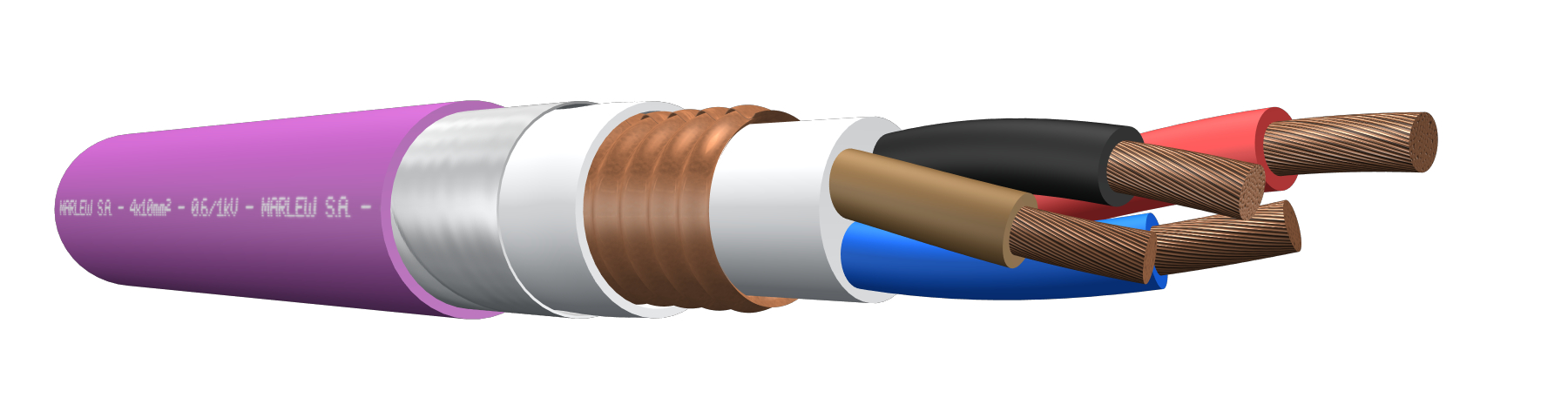
Fixed power distribution networks in high voltage substations (SSEE), its shielding allows adequate filtering of electromagnetic interference at frequencies up to 1 MHz. For Alternating Current (50/60Hz), for single-phase systems (220/110V), three-phase systems (380/190V) and systems with voltages up to 1kV. For Direct Current, used in systems with voltages up to 1.5kV Installed in aerial trays, gutters or conduits, buried in ducts or directly buried. It has additional mechanical protection.
Features
Temperature rating: 70ºC (operating), 160°C (short circuit)
Voltage rating: 600/1000V AC, maximum 1200V AC / 1500V DC
Construction requirements: As per IRAM 2178-1 – IEC 60502-1
Conductor requirements: As per IRAM NM 280 – IEC 60228
Conductor: Annealed electrolytic copper; flexible, class 5 stranding
Insulation: PVC
Bedding: PVC
Shield: Corrugated copper tape longitudinal overlapping wrap
Inner sheath: PVC
Armour: Double aluminium tape spiral wrap (in single-conductor cables) and double zinc-plated steel tape spiral wrap (in multiconductor cables) (galvanized). The use of armored single core cables in A.C. requires that the armature be of a non-magnetic material
Sheath: PVC, fire-retardant
Fire requirements: As per IEC 60332-3-24
EMC requirements: Transfer impedance lower than 2 ohm/km up to 1MHz (as per IRAM 63020; HN 33-S-34)

Corrugated copper shield

Fire-retardant

Flexible stranded conductors
Sequentially marked

Industrial applications

Tray cable
Identification
| Standard | ||
|---|---|---|
| Sheath | Conductors | |
| 1 Conductor |  |  |
| 2 Conductors | |  |
| 3 Conductors | |   |
| 4 Conductors | | |
Instalation


Constructive variants
The information provided corresponds to the standard version, and different alternatives of insulation and / or covering materials can be used upon request.
ELECTRICAL CHARACTERISTICS
Resistances and reactance
| Nominal cross-section (mm²) | Electrical resistance in D.C. at 20°C (Ohm/km) | Electrical resistance in C.C. at 70°C (Ohm/km) | Inductive reactance at 50Hz (Ohm/Km) | ||||
|---|---|---|---|---|---|---|---|
| 1 Conductor (1) | 1 Conductors (2) | 1 Conductors (3) | Multiconductor (4) | 4 Conductors (5) | |||
 |  |  |  |  | |||
| 1 | 19.5 | 23.33 | -- | -- | -- | 0.111 | 0.119 |
| 1.5 | 13.3 | 15.91 | -- | -- | -- | 0.104 | 0.112 |
| 2.5 | 7.98 | 9.55 | -- | -- | -- | 0.097 | 0.104 |
| 4 | 4.95 | 5.92 | -- | -- | -- | 0.097 | 0.104 |
| 6 | 3.3 | 3.95 | 0.172 | 0.215 | 0.157 | 0.091 | 0.098 |
| 10 | 1.91 | 2.29 | 0.153 | 0.197 | 0.139 | 0.084 | 0.092 |
| 16 | 1.21 | 1.45 | 0.14 | 0.184 | 0.126 | 0.08 | 0.088 |
| 25 | 0.78 | 0.93 | 0.135 | 0.179 | 0.121 | 0.08 | 0.087 |
| 35 | 0.554 | 0.663 | 0.129 | 0.173 | 0.115 | 0.078 | 0.085 |
| 50 | 0.386 | 0.462 | 0.124 | 0.167 | 0.109 | 0.077 | 0.085 |
| 70 | 0.272 | 0.326 | 0.118 | 0.162 | 0.104 | 0.074 | 0.082 |
| 95 | 0.206 | 0.248 | 0.114 | 0.158 | 0.1 | 0.074 | 0.081 |
| 120 | 0.161 | 0.194 | 0.11 | 0.154 | 0.096 | 0.072 | 0.08 |
| 150 | 0.129 | 0.156 | 0.108 | 0.152 | 0.094 | 0.072 | 0.08 |
| 185 | 0.106 | 0.129 | 0.108 | 0.151 | 0.093 | 0.072 | 0.08 |
| 240 | 0.0801 | 0.0993 | 0.105 | 0.148 | 0.09 | 0.072 | 0.079 |
| 300 | 0.0641 | 0.081 | 0.102 | 0.146 | 0.088 | 0.071 | 0.079 |
| 400 | 0.0486 | 0.0637 | 0.102 | 0.145 | 0.087 | -- | -- |
| 500 | 0.0384 | 0.0527 | 0.1 | 0.143 | 0.085 | -- | -- |
| 630 | 0.0287 | 0.0429 | 0.098 | 0.141 | 0.083 | -- | -- |
(1) Three single conductor cables displayed in flat, in contact with each other. (2) Three single conductor cables displayed in flat, separated by 1 diameter between each other. (3) Three single-conductor cables displayed in a trefoil in contact with each other. (4) Calculation of Inductive reactance valid for two-conductor and three conductor cables. (5) Calculation of Inductive reactance valid for four-conductor cables.
Intensity of admissible currents
| Nominal cross-section (mm²) | Current-carrying capacity of cables in free air at 40°C as per IEC 364-5-523. Single-conductors cable up to 16mm² in contact with each other, displayed in unperforated trays, remaining cross-sections, single-conductors displays and formations in cable ladder or perforated cable trays (Ampere) | Current-carrying capacity of cables directly buried at 25°C soil temperature and soil thermal resistance of 1 km/W as per IEC 364-5-523. (Ampere) | |||||||
|---|---|---|---|---|---|---|---|---|---|
| 1 Conductor (1) | 1 Conductors (2) | 1 Conductors (3) | 2 Conductors | Multiconductor (4) | 1 Conductor (1) | 1 Conductors (2) | 2 Conductors | Multiconductor (4) | |
| | | |  |  | | | | | |
| 1 | -- | -- | -- | -- | -- | -- | -- | -- | -- |
| 1.5 | -- | -- | -- | 18.1 | 15.3 | -- | -- | 28 | 24 |
| 2.5 | -- | -- | -- | 25 | 21 | -- | -- | 37 | 32 |
| 4 | -- | -- | -- | 33 | 29 | -- | -- | 48 | 42 |
| 6 | 34 | -- | -- | 42 | 35 | 60 | 64 | 62 | 52 |
| 10 | 48 | -- | -- | 58 | 49 | 80 | 85 | 84 | 70 |
| 16 | 63 | -- | -- | 78 | 67 | 103 | 110 | 106 | 90 |
| 25 | 94 | 121 | 91 | 98 | 84 | 133 | 142 | 137 | 117 |
| 35 | 118 | 149 | 113 | 123 | 105 | 160 | 171 | 164 | 140 |
| 50 | 143 | 181 | 138 | 149 | 126 | 186 | 199 | 197 | 164 |
| 70 | 186 | 232 | 179 | 192 | 162 | 230 | 246 | 241 | 200 |
| 95 | 227 | 282 | 219 | 233 | 197 | 276 | 295 | 291 | 241 |
| 120 | 265 | 328 | 255 | 271 | 228 | 314 | 335 | 333 | 276 |
| 150 | 308 | 377 | 295 | 314 | 263 | 352 | 376 | 373 | 309 |
| 185 | 352 | 430 | 338 | 358 | 301 | 398 | 426 | 423 | 351 |
| 240 | 419 | 508 | 401 | 425 | 355 | 464 | 496 | 493 | 407 |
| 300 | 485 | 586 | 464 | 490 | 410 | 525 | 562 | 558 | 460 |
| 400 | 569 | 704 | 542 | -- | -- | 600 | 642 | -- | -- |
| 500 | 652 | 811 | 619 | -- | -- | 695 | 744 | -- | -- |
| 630 | 748 | 941 | 707 | -- | -- | 796 | 852 | -- | -- |
(1) Three single conductor cables displayed in flat, in contact with each other. (2) Three single conductor cables displayed in flat, separated by 1 diameter between each other. (3) Three single-conductor cables displayed in a trefoil in contact with each other. (4) The values of current-carrying capacity informed, correspond to three-conductor, four-conductor.
DIMENSIONS & WEIGHT
| Cable formation N° Cond. x cross-section (mm²) | Diameter below armour mm | External diameter mm | Weight kg/km | Code |
|---|---|---|---|---|
| 1x16 | 14.6 | 19 | 592 | GV 1160 D |
| 1x25 | 16.1 | 20.7 | 725 | GV 1250 D |
| 1x35 | 17.6 | 22.2 | 862 | GV 1350 D |
| 1x50 | 19.1 | 23.7 | 1032 | GV 1500 D |
| 1x70 | 21.1 | 25.7 | 1277 | GV 1700 D |
| 1x95 | 23.1 | 27.9 | 1544 | GV 1950 D |
| 1x120 | 25.1 | 30.1 | 1883 | GV 11200 D |
| 1x150 | 27.6 | 32.6 | 2229 | GV 11500 D |
| 1x185 | 30.1 | 35.3 | 2663 | GV 11850 D |
| 1x240 | 33.6 | 39 | 3380 | GV 12400 D |
| 1x300 | 36.6 | 42.2 | 3998 | GV 13000 D |
| 1x400 | 40.6 | 46.4 | 5221 | GV 14000 D |
| 1x500 | 44.6 | 50.6 | 6497 | GV 15000 D |
| 1x630 | 47.6 | 53.8 | 7845 | GV 16300 D |
| 2x4 | 16.6 | 20.4 | 668 | GV 0240 F |
| 2x6 | 17.6 | 21.4 | 744 | GV 0260 F |
| 2x10 | 19.6 | 23.4 | 906 | GV 2100 F |
| 2x16 | 21.6 | 25.4 | 1101 | GV 2160 F |
| 2x25 | 25.1 | 28.9 | 1447 | GV 2250 F |
| 2x35 | 27.6 | 31.4 | 1759 | GV 2350 F |
| 2x50 | 31.1 | 35.1 | 2254 | GV 2500 F |
| 2x70 | 34.6 | 38.8 | 2845 | GV 2700 F |
| 2x95 | 38.6 | 44.4 | 4118 | GV 2950 F |
| 2x120 | 43.6 | 49.6 | 5161 | GV 21200 F |
| 2x150 | 47.6 | 53.8 | 6079 | GV 21500 F |
| 2x185 | 52.6 | 59 | 7299 | GV 21850 F |
| 2x240 | 58.6 | 65.4 | 9087 | GV 22400 F |
| 3x2.5 | 15.1 | 18.9 | 591 | GV 0325 F |
| 3x4 | 17.6 | 21.4 | 742 | GV 0340 F |
| 3x6 | 18.6 | 22.4 | 831 | GV 0360 F |
| 3x10 | 20.6 | 24.4 | 1024 | GV 3100 F |
| 3x16 | 23.1 | 26.9 | 1294 | GV 3160 F |
| 3x25 | 26.6 | 30.4 | 1707 | GV 3250 F |
| 3x35 | 29.1 | 33.1 | 2112 | GV 3350 F |
| 3x50 | 33.6 | 37.8 | 2810 | GV 3500 F |
| 3x70 | 37.6 | 43.2 | 4111 | GV 3700 F |
| 3x95 | 41.6 | 47.6 | 5084 | GV 3950 F |
| 3x120 | 45.6 | 51.8 | 6226 | GV 31200 F |
| 3x150 | 51.6 | 58 | 7628 | GV 31500 F |
| 3x185 | 55.6 | 62.2 | 8958 | GV 31850 F |
| 3x240 | 62.6 | 69.6 | 11323 | GV 32400 F |
| 4x2.5 | 16.1 | 19.9 | 650 | GV 0425 F |
| 4x4 | 18.6 | 22.4 | 814 | GV 0440 F |
| 4x6 | 19.6 | 23.4 | 917 | GV 0460 F |
| 4x10 | 22.1 | 25.9 | 1170 | GV 4100 F |
| 4x16 | 24.6 | 28.4 | 1481 | GV 4160 F |
| 3x25+1x16 | 28.1 | 31.9 | 1905 | GV 2516 F |
| 3x35+1x16 | 30.1 | 34.1 | 2279 | GV 3516 F |
| 3x50+1x25 | 34.6 | 38.8 | 3024 | GV 5025 F |
| 3x70+1x35 | 38.6 | 44.4 | 4477 | GV 7035 F |
| 3x95+1x50 | 43.6 | 49.6 | 5608 | GV 9550 F |
| 3x120+1x70 | 48.6 | 55 | 7052 | GV 12070 F |
| 3x150+1x70 | 52.6 | 59 | 8176 | GV 15070 F |
| 3x185+1x95 | 57.6 | 64.4 | 9800 | GV 18595 F |
| 3x25+2x16 | 29.6 | 33.6 | 2119 | GV 25216 F |
| 3x35+2x16 | 31.6 | 35.6 | 2485 | GV 35216 F |
| 3x50+2x25 | 36.6 | 41 | 3356 | GV 50225 F |
| 3x70+2x35 | 40.6 | 46.4 | 4905 | GV 70235 F |
| 3x95+2x50 | 45.6 | 51.8 | 6161 | GV 95250 F |
| 3x120+2x70 | 51.6 | 58 | 7874 | GV 120270 F |
| 3x150+2x70 | 54.6 | 61.2 | 8900 | GV 150270 F |
| 3x185+2x95 | 60.6 | 67.6 | 10809 | GV 185295 F |