 series GF
Multiconductor
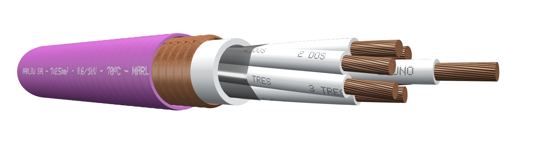


Corrugated copper shielding
Control, signalling, measuring and protective equipment, electric controls of high voltage substations (SSEE), its shielding allows adequate filtering of electromagnetic interference at frequencies up to 1 MHz. Installed in aerial trays, gutters or conduits, under roof or ladder under roof, buried in ducts or directly buried.
Features
Temperature rating: 70ºC (operating), 160°C (short circuit)
Voltage rating: 600/1000V AC, maximum 1200V AC / 1500V DC
Construction requirements: As per IRAM 2178-1 – IEC 60502-1
Conductor requirements: As per IRAM NM 280 – IEC 60228
Conductor: Annealed electrolytic copper - Flexible stranding class 5
Insulation: PVC
Bedding: PVC
Shield: Corrugated copper tape longitudinal overlapping wrap
Sheath: PVC, fire-retardant
Fire requirements: As per IEC 60332-3-24
EMC requirements: Transfer impedance lower than 2 ohm/km up to 1MHz (as per IRAM 63020; HN 33-S-34)
Corrugated copper shield
Fire-retardant

Flexible stranded conductors
Sequentially marked

Industrial applications

Tray cable
Identification
| Standard | ||
|---|---|---|
| Sheath | Conductors | |
| Multiconductors |  |  with alpha-numerically with alpha-numerically |
Instalation

Constructive variants
The information provided corresponds to the standard version, and different alternatives of insulation and / or covering materials can be used upon request.
ELECTRICAL CHARACTERISTICS
Resistances and intensity of admissible currents
| Nominal cross-section sq mm² | Electrical resistance at 20°C in C.C. Ohm/km | Electrical resistance at 70°C in C.A. Ohm/km | Current-carrying capacity in free air. At 40°C as per IEC 364-5-523. Formations in perforated trays or ladder type. (Ampere) | ||||||
|---|---|---|---|---|---|---|---|---|---|
| 2x | 4x | 7x | 10x | 19x | 30x | 48x | |||
| 1 | 19.5 | 23.3 | -- | -- | -- | -- | -- | -- | -- |
| 1.5 | 13.3 | 15.9 | 18.1 | 15.3 | 12.7 | 9.1 | 9.1 | 8.1 | 6.3 |
| 2.5 | 7.98 | 9.55 | 25 | 21 | 17.5 | 12.5 | 12.5 | 11.3 | 8.8 |
| 4 | 4.95 | 5.92 | 33 | 29 | 23.1 | 16.5 | 16.5 | 14.9 | -- |
As from seven-conductors, we’ve additionally applied the correction factor for more than three conductors the chart 310.15 (B)(3)(a) of the NFPA70.
DIMENSIONS & WEIGHT
| Cable formation N° Cond. x cross-section (mm²) | External diameter mm | Weight kg/km | Code |
|---|---|---|---|
| 2x1 | 14.6 | 319 | GF 0210 |
| 3x1 | 14.6 | 324 | GF 0310 |
| 4x1 | 14.6 | 327 | GF 0410 |
| 5x1 | 15.1 | 348 | GF 0510 |
| 7x1 | 16.1 | 395 | GF 0710 |
| 10x1 | 18.1 | 471 | GF 1010 |
| 12x1 | 19.1 | 517 | GF 1210 |
| 14x1 | 20.1 | 566 | GF 1410 |
| 19x1 | 22.1 | 676 | GF 1910 |
| 24x1 | 24.1 | 794 | GF 2410 |
| 30x1 | 25.6 | 894 | GF 3010 |
| 37x1 | 28.1 | 1064 | GF 3710 |
| 48x1 | 30.6 | 1275 | GF 4810 |
| 2x1.5 | 14.6 | 324 | GF 0215 |
| 3x1.5 | 14.6 | 332 | GF 0315 |
| 4x1.5 | 15.1 | 354 | GF 0415 |
| 5x1.5 | 16.1 | 396 | GF 0515 |
| 7x1.5 | 17.1 | 451 | GF 0715 |
| 10x1.5 | 19.1 | 535 | GF 1015 |
| 12x1.5 | 20.1 | 588 | GF 1215 |
| 14x1.5 | 21.1 | 646 | GF 1415 |
| 19x1.5 | 23.6 | 797 | GF 1915 |
| 24x1.5 | 25.6 | 934 | GF 2415 |
| 30x1.5 | 27.6 | 1085 | GF 3015 |
| 37x1.5 | 29.6 | 1256 | GF 3715 |
| 48x1.5 | 33.8 | 1637 | GF 4815 |
| 2x2.5 | 14.6 | 336 | GF 0225 |
| 3x2.5 | 15.1 | 366 | GF 0325 |
| 4x2.5 | 16.1 | 411 | GF 0425 |
| 5x2.5 | 17.1 | 461 | GF 0525 |
| 7x2.5 | 18.1 | 531 | GF 0725 |
| 10x2.5 | 20.6 | 650 | GF 1025 |
| 12x2.5 | 22.1 | 743 | GF 1225 |
| 14x2.5 | 23.1 | 814 | GF 1425 |
| 19x2.5 | 25.6 | 1003 | GF 1925 |
| 24x2.5 | 28.1 | 1205 | GF 2425 |
| 30x2.5 | 30.1 | 1404 | GF 3025 |
| 37x2.5 | 33.8 | 1764 | GF 3725 |
| 48x2.5 | 37 | 2127 | GF 4825 |
| 2x4 | 16.6 | 422 | GF 0240 |
| 3x4 | 17.6 | 483 | GF 0340 |
| 4x4 | 18.6 | 541 | GF 0440 |
| 5x4 | 19.6 | 606 | GF 0540 |
| 7x4 | 21.1 | 725 | GF 0740 |
| 10x4 | 24.1 | 892 | GF 1040 |
| 12x4 | 25.6 | 1010 | GF 1240 |
| 14x4 | 27.1 | 1132 | GF 1440 |
| 19x4 | 30.6 | 1460 | GF 1940 |
| 24x4 | 34 | 1809 | GF 2440 |
| 30x4 | 37 | 2143 | GF 3040 |
| 37x4 | 41.2 | 2792 | GF 3740 |