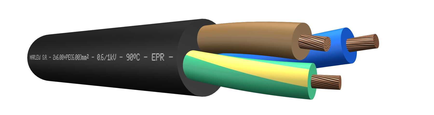
 series BSRr U
Rounded Single-conductor to four-conductor cables
Power supply of submersible pumps in aggressive environmental conditions such as sewage, contaminated water, various chemicals, oils and salts. Suitable for work in hydrocarbon exploration areas. For Alternating Current (50/60Hz), for single-phase systems (220/110V), three-phase systems (380/190V) and systems with voltages up to 1kV. For Direct Current, used in systems with voltages up to 1.5kV
Features
Temperature ratings: 90°C (Operating) – 130°C (Overload) – 25 0°C (Short-Circuit)
Voltage rating: 600/1000 Volt A.C. – 1200 Volt A.C. (Max) – 1500 Volt D.C.
Construction requirements: IRAM 63007
Conductor requirements: IRAM NM 280 – IEC 60228
Conductor: Annealed electrolytic copper - Flexible stranding class 5
Insulation: EPR
Assembly: Conductors gathered
Sheath: Flame retardant and chemicals resistant polyurethane
Fire requirements: As per IEC 60332-1
Oils requirements: As per ICEA S 73-532
Hydrocarbons requirements: As pre UIC 895 OR
Outdoors requirements: As per UL 2556 (rayos UV)

Flame retardant

Grounded conductor

High flexibility

Hydrocarbon resistant

UV resistant

Submersible Pump
Identification
| Standard | ||
|---|---|---|
| Sheath | Conductors | |
| 1 Conductor |  |  |
| 2 Conductors | |  |
| 3 Conductors | |  |
| 4 Conductors | |  |
Instalation
Constructive variants
The information provided corresponds to the standard version, and different alternatives of insulation and / or covering can be used upon request.
ELECTRICAL CHARACTERISTICS
Resistances and reactance
| Nominal cross-section (mm²) | Class 5. Electrical resistance in D.C. at 20°C (Ohm/km) | Electrical resistance in C.C. at 90°C (Ohm/km) | Inductive reactance at 50Hz (Ohm/Km) | ||||
|---|---|---|---|---|---|---|---|
| 1 Conductor (1) | 1 Conductor (2) | 1 Conductor (3) | Multiconductor (4) | 4 Conductors (5) | |||
 |  |  |  |  | |||
| 1.5 | 13.3 | 16.96 | -- | -- | -- | 0.118 | 0.126 |
| 2.5 | 7.98 | 10.18 | -- | -- | -- | 0.109 | 0.117 |
| 4 | 4.95 | 6.31 | -- | -- | -- | -- | 0.11 |
| 6 | 3.3 | 4.21 | -- | -- | -- | -- | 0.103 |
| 10 | 1.91 | 2.44 | -- | -- | -- | -- | 0.099 |
| 16 | 1.21 | 1.54 | -- | -- | -- | -- | 0.094 |
| 25 | 0.78 | 0.99 | 0.117 | 0.161 | 0.103 | -- | 0.094 |
| 35 | 0.554 | 0.71 | 0.13 | 0.156 | 0.098 | -- | 0.091 |
| 50 | 0.386 | 0.49 | 0.11 | 0.153 | 0.095 | -- | 0.09 |
| 70 | 0.272 | 0.35 | 0.104 | 0.148 | 0.09 | -- | 0.086 |
| 95 | 0.206 | 0.26 | 0.103 | 0.147 | 0.088 | -- | 0.086 |
| 120 | 0.161 | 0.21 | 0.101 | 0.144 | 0.086 | -- | -- |
| 150 | 0.129 | 0.17 | 0.099 | 0.143 | 0.085 | -- | -- |
(1) Three single conductor cables displayed in flat, in contact with each other. (2) Three single conductor cables displayed in flat, separated by 1 diameter between each other. (3) Three single-conductor cables displayed in a trefoil in contact with each other. (4) Calculation of Inductive reactance valid for two-conductor and three conductor cables. (5) Calculation of Inductive reactance valid for four-conductor cables.
Intensity of admissible currents
| Nominal cross-section (mm²) | Current-carrying capacity of cables in free air at 40°C as per IEC 364-5-523.Single-conductors cable up to 16mm² in contact with each other, displayed in unperforated trays, remaining cross-sections, single-conductors displays and formations in cable ladder or perforated cable trays (Ampere) | Current-carrying capacity of cables directly buried at 25°C soil temperature and soil thermal resistance of 1 km/W as per IEC 364-5-523 (Ampere) | |||||||
|---|---|---|---|---|---|---|---|---|---|
| Unipolar (1) | Unipolar (2) | Unipolar (3) | Bipolar | Multipolar | Unipolar (1) | Unipolar (2) | Bipolar | Multipolar | |
| | | |  |  | | | | | |
| 1.5 | -- | -- | -- | 23 | 20 | -- | -- | 32 | 28 |
| 2.5 | -- | -- | -- | 31 | 28 | -- | -- | 44 | 37 |
| 4 | -- | -- | -- | -- | 36 | -- | -- | -- | 48 |
| 6 | -- | -- | -- | -- | 47 | -- | -- | -- | 61 |
| 10 | -- | -- | -- | -- | 65 | -- | -- | -- | 83 |
| 16 | -- | -- | -- | -- | 86 | -- | -- | -- | 107 |
| 25 | 122 | 158 | 117 | -- | 109 | 157 | 168 | -- | 141 |
| 35 | 152 | 196 | 146 | -- | 137 | 188 | 201 | -- | 168 |
| 50 | 187 | 238 | 179 | -- | 166 | 220 | 235 | -- | 199 |
| 70 | 241 | 305 | 232 | -- | 213 | 271 | 290 | -- | 243 |
| 95 | 295 | 371 | 283 | -- | 257 | 326 | 349 | -- | 293 |
| 120 | 346 | 432 | 332 | -- | -- | 371 | 397 | -- | -- |
| 150 | 401 | 499 | 384 | -- | -- | 415 | 444 | -- | -- |
(1) Three single conductor cables displayed in flat, in contact with each other. (2) Three single conductor cables displayed in flat, separated by 1 diameter between each other. (3) Three single-conductor cables displayed in a trefoil in contact with each other.